
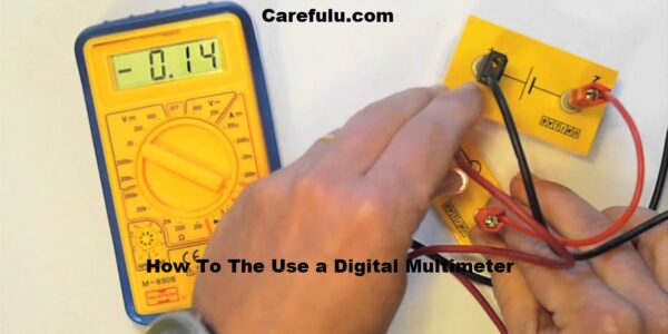
How To The Use a Digital Multimeter
 For all latest news, follow The carefulu Google News channel.
What is a Digital Multimeter and What Does it Measure?
A digital multimeter is an important tool for checking out, diagnosing, and troubleshooting electric circuits, components, and devices. The first digital multimeter changed into delivered within the overdue Nineteen Seventies and has been confirmed to be a good deal greater correct and dependable than older needle-primarily based analog meters.
It is mostly used to measure voltage (volts), modern (amps), and resistance (ohms). But this is just the start of what this amazingly effective tool can do. Below are the not-unusual uses of your virtual multimeter.
Note that the commands are given here practice to most multimeters. However, the accurate method and the way the screen may be examined may additionally range slightly relying on the features and capabilities of your particular device.
A Digital Multimeter is a check device used to measure or more electric values—basically voltage (volts), current (amps), and resistance (ohms). It is a widespread diagnostic device for technicians in the electric/digital industries.[/ctt]
Before leaping into How To Use a Digital Multimeter, examine Fluke’s promotional articles on multimeters as nicely. They will come up with robust feedback on what a multimeter is and what it could do as well as maintain studying to get some guidelines from our favorite electricians.
How To Use a Digital Multimeter
How to Measure Voltage with Digital Multimeter
There are typically two separate voltages that may be measured by a multimeter. One is DC voltage and the other is AC voltage.
All electronic devices perform at DC voltage (conventional AC could be transformed to DC) and subsequently, DC voltage is the most measurable parameter. The multimeter can measure both AC and DC voltages. Let’s start with DC voltage.
How to Measure DC Voltage with Digital Multimeter
Two matters need to be tested on a multimeter earlier than proceeding with any measurement. These are the position of the test lead (a.Okay.A test probe) and the mode/variety choice.
By default, the black check lead role must be within the COM slot and the pink take-a-look-at lead should be within the V slot. This role will handiest exchange if we degree the contemporary.
So, the black take a look at lead ought to be within the COM slot, and the pink lead inside the V slot to measure a voltage. Oh, the black check lead needs to be in the COM slot and the crimson leads inside the V slot to degree a voltage.
Now we need to pick out the mode of usage of a knot-like controller inside the center of the multimeter. We should search for the DC voltage image and pick out a selection beneath it.
By default, the range could be 200MV, 2V, 20V, 200V, and 600V. You can select the range based on the voltage stage you are planning to a degree. And don’t worry if you pick out a lower variety you could continually hit and strive but it doesn’t explode.
For example, if you measure 35V and if you preserve it inside the 20V variety, you may study meter 1, this means that you must choose a higher voltage variety for 200V in this situation.
I have located the meter on analyzing the DC voltage inside the 20V range. After putting the meter, we can simplest place the probes on the terminal on which we have to measure the voltage.
. Place the pink lead at the wonderful terminal and the Black result in the poor terminal and you’ll get the value of voltage. If you get a value contrary to the pole of the cable, it’ll be accompanied by a poor signal, continually use searches on the perfect pole to avoid errors.
When debugging programs, you may degree any battery, DC adapter, telephone charger or even voltage across each factor of a circuit.
How to Measure AC Voltage with Digital Multimeter
AC voltage is hardly ever measured using a digital multimeter however it is still vital where AC mains are worried. Place the pink lead inside the V slot and the black lead within the COM slot to measure the AC voltage.
Now set the mode for the use of the knock, we need to place it inside the AC voltage image. Normally we are able to have tiers for AC voltage, and they’re 200V and 600V.
For measuring AC voltage in India which is 220V, we need to put it in 600V mode. The size manner is much like measuring DC voltage, however, we don’t have any variations here because of working with AC.
How to Check Continuity with Digital Multimeter
Another vital and useful characteristic of a multimeter is to test the continuity. This is a lifesaver device that enables debug electronics, whether it’s your new PCB or an easy breadboard connection you can use the continuity device to test if there’s any connection between the two terminals.
It can also be used to detect damaged wires. Check for continuity of any twine or circuit, place the black probe in the COM slot and the purple probe in the V slot, then take away the knot as a continuity image. To test the continuity between Terminal A and Terminal B, region one probe (any probe) in Terminal A and the opposite in Terminal B.
If there may be a connection between Terminal A and Terminal B, the meter will study 0 and you’ll get a “beep” sound. You will not obtain a beep without a connection.
How to Measure Resistance with Digital Multimeter
The most generally used and crucial factor of electronics is resistors. There are different styles of registers to be had based on their energy rating and resistance cost; shade codes will specify the cost of every resistor.
It is vital to learn how to read the price of a resistor and the usage of colour code however there may be some troubles which are very hard to study the coloration. In this case, we are able to without problems use a multimeter to study the resistance value of the resistor.
To degree resistance with a multimeter, make certain that the black probe is inside the COM slot and the crimson probe is inside the V slot. Now, turn the knob to the resistance image.
Again we’ve got a number of 200Ω to 2MΩ, choose anything you want, putting it at 20k exceptional. You can usually strive for distinctive levels to get the proper variety suitable to your resistor.
Testing Batteries
A new battery will produce slightly extra than its rated voltage (for this battery, 1. Five volts). Note that this meter has different settings: Use the voltage mode of your meter to test the battery output, beginning with the most effective, maximum fundamental take a look at one volt, the alternating contemporary, and the other for the direct contemporary of the volt.
First, plug the black probe of the meter into the marked jack – COM (common). Insert the purple probe labeled Volt or + V into the jack (next to the V, you’ll additionally see a symbol that looks like an inverted horse, we’ll get to it in a minute).
Most cutting-edge meters color-coding the jacks make this setup all but stupid. The black trendy investigation goes into Black Jack; The purple probe is going to Red Jack.
Now transfer (dial) the volt DC; Because batteries supply direct modern (DC), no longer present-day alternatives (AC). Hold the crimson probe tip in opposition to the battery’s fine (+) outside-fashioned terminal and preserve the black probe against the ward negative (-) internal-shaped terminal.
The battery voltage will fall on the meter show screen. For instance, a totally charged AA battery has to read at least 1.5 volts. And you could use your digital multimeter to check without a doubt any battery, from AAAS to vehicle batteries.
Note that the method described above most effectively tests the voltage, no longer the capability of the battery to supply current under load. The test offers you a tough idea of whether the battery is good, shot, or wishes to be charged.
Testing Electrical Outlets
Here’s a way to determine if your property wall shops are providing the proper voltage, that’s one hundred twenty volts in maximum cutting-edge houses. Plug the black probe into the meter’s black COM jack and the red probe into the pink volts jack.
Then switch on the rotary turn on the volt AC (VAC), which is likewise indicated by a wavy wave line on the dial. Press the end of the pink probe into the fast (hot) of the 2 vertical slots of the opening.
Place the black probe in the long slot (impartial). Check the readout at the meter display screen. A well-functioning outlet should produce a hundred and ten to one hundred twenty volts.
Next, remove the black probe from the opening – leaving the purple probe – insert the black probe into the small, spherical hollow (ground) at the bottom of the 2 slots. The analysis should continue to be the equal. If this isn’t always the case, the outlet is incorrectly wired or the ground might be missing; An electronic call.
Testing a Wall Switch
Got a faulty ceiling mild? Here’s a way to determine if a hassle has a transfer. First, flip off the electricity to the transfer, put off the cover plate and unscrew the switch from the twine. Before disconnecting the wires, label them or take a picture along with your phone so you can join them nicely.
Loosen the transfer terminal screws, unhook the wires from the wires and dispose of the switch. Rotate the meter dial in ohm putting. Set the resistance restriction at X1. If your meter has auto-range, you could inform the car-ranging meter whilst you switch at the dial within the Vault AC (VAC) placing, the phrase “car” seems on the screen) skip this step.
Plug the black inquiry into the COM jack and the red probe into the pink V jack. To check a unmarried-pole transfer (the handiest type; it has brass screws and a green screw). Flip the transfer to the off function.
Now contact the probe of the meter with the brass screw terminal subsequent to the transfer – it does now not be counted which screw will touch which screw.
As soon as the switch is grew to become off it’d be pleasant if you got a text of the OL (you can also get different readings, which includes 99999 or a symbol like this or also: L). It manner overload or over-limit; The resistance is so excessive that it can not be measured.
At first, this will now not appear understandable (you suspect the meter will examine zero ohms), but the meter tells you that when no internal contacts contact the inner of the switch, the resistance across the open contacts is so massive that the meter can’t read it. Now flip the switch on and the meter need to read much less than one ohm.
If this isn’t the case, the transfer should be defective and replaced. Another simple test is to rotate the meter dial inside the function for continuity. It manner an uninterrupted electric path.
The image for continuity at the face of the meter is an altar form that suggests that the sound extends from factor to factor. Attach the meter throughout the transfer connections and turn the transfer up and down.
The switch is right if the meter beeps with the transfer with the on role. If the meter turns the switch on, the transfer is horrific without beeping the meter.
Testing Extension Cords
Sometimes it’s clever to apply your meter to test vintage extension cords due to the fact broken cords can push you or begin a hearth. Start via plugging the extension wire from the wall and turning the meter dial into an ohm putting.
To have a look at the ground of the wire, press the red probe into the small hole within the woman stop of the cord. Then touch the longest round (ground) probe extending from the male side. The resistance of an uninterrupted circuit measured from those two ends may be 8 ohms or less.
Now contact the red probe at every flat prompt at the male end to make certain the OL study. In this style the twine should have an open circuit while analyzed; There must be no touch between the floor pin and the connecting wire to any of the other wires in the cord.
Next, insert the red probe into the fast (warm) slot on the female cease of the twine. Touch the black probe from the narrow flat edge to the male quit. The electrical continuity via the cord could have a resistance of .8 ohms or much less.
Then contact the black probe until the wide plane vibrates after which the round fork, the meter should display no continuity and an O.L. Display to examine those two phrases.
Finally, take the red probe and press it into the longer (impartial) slot on the lady end of the twine. Look at the black probe and touch the pendant of the spacious flat. Continuity can have a resistance of .8 ohms or much less.
Touch the fast prong and then the round prong black probe for an O.L. Continue reading. After ensuring that the twine has no shorts, run a voltage test.
Plug the cord into the electric outlet and flip the meter dial on the volt AC. Insert the black probe into the spherical hollow on the lady quit of the cord and press the red probe into the slender slot. You should have a reading around 120 volts.
Now move the crimson probe to the long (neutral) slot to ensure you read approximately. 1 millivolt (there may be a negligible voltage between the floor and impartial of the hole and the ground and neutral of the twine).
Leave the red probe in the lengthy slot and circulate the black probe within the quick slot to examine a voltage of about a hundred and twenty volts, making sure that the extension twine is in appropriate condition.
Reading Temperatures
In addition to all its high-quality electro-trying out capabilities, maximum contemporary virtual multimeters also can take temperature readings. In temperature, mode rotates the meter dial, then press the select button to toggle between Fahrenheit and Celsius.
Plug the thermocouple into the meter to examine the air temperature, or insert the temperature probe to take temperature readings of beverages, gels or to music the floor temperature of the gasoline dryer. You can observe the temperature cycle of the device without touching it along with your arms.
Fact Check
We strive for equity and accuracy of How To Use a Digital Multimeter. If you study something that doesn’t look right, contact us!


